
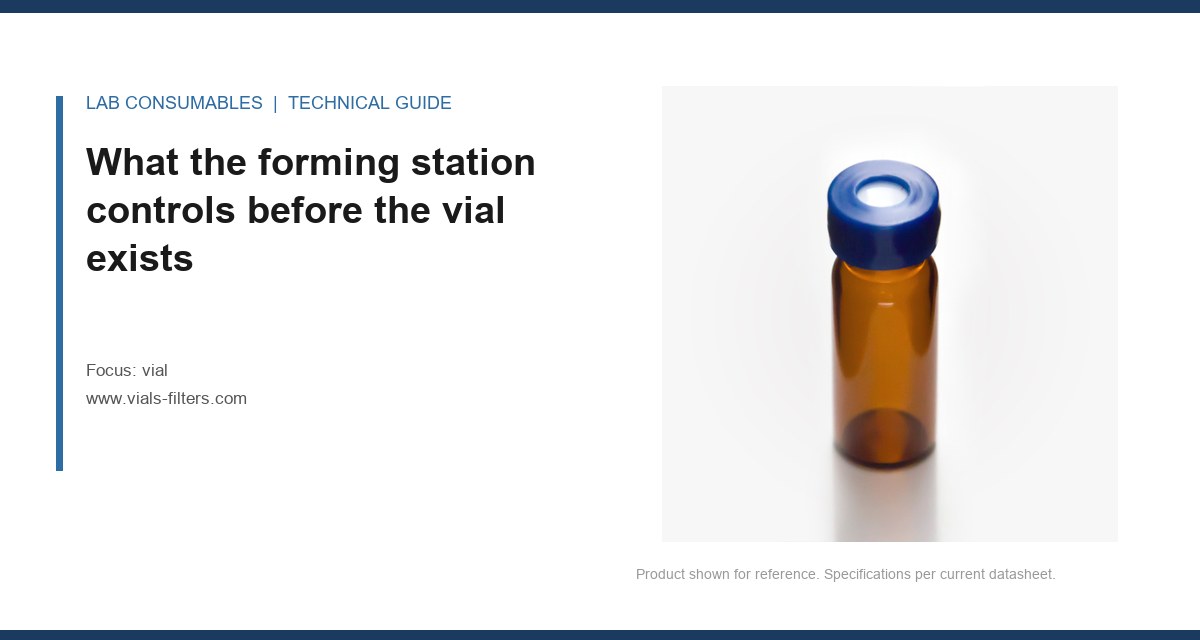
A 2 mL HPLC vial lot came back from a customer with a 4.7% RSD on peak area across 100 injections. Same method, same autosampler, same column. The previous lot ran 0.8%. The difference was not the glass type, not the certificate of analysis, not the country of origin. It was a 0.04 mm shift in the inner bore taper at the neck that no incoming QC spec caught. That is what a vial factory actually controls on the line when it is doing its job, and what it misses when it is not. This article walks the manufacturing floor station by station and separates what is closed-loop controlled from what is only checked at the end, because those two categories are not the same thing and procurement rarely asks the question that tells them apart.
Vial manufacturing starts with glass tubing, not with molten glass. The tubing is drawn to a target outer diameter, usually 12.00 mm for a 12×32 mm autosampler vial, with a wall thickness of 0.90 to 1.10 mm depending on the glass type. The forming station is a vertical turret with multiple mandrels. Each mandrel shapes the vial bottom, the body, and the neck in one rotation. The parameters that matter here are mandrel temperature, glass feed rate, and the profile of the flame that softens the tubing.
Mandrel temperature is closed-loop controlled. A thermocouple sits inside each mandrel and the controller holds it within ±5°C of the setpoint. If the mandrel runs 10°C cold, the vial bottom does not flow fully into the mold and you get a concave base. That concave base changes the fill volume by 30 to 50 µL and can cause the autosampler needle to bottom out before the needle tip reaches the intended depth. If the mandrel runs 10°C hot, the glass sticks and the inner surface picks up micro-roughness that later shows up as carryover.
Glass feed rate is also closed-loop. The tubing is pushed through the flame at a constant linear speed, typically 4 to 6 meters per minute for 12 mm tubing. A servo encoder on the feed rollers reports position back to the turret controller. The controller adjusts roller speed to hold the feed rate within ±0.5% of setpoint. This matters because the vial body length is set by the dwell time in the forming zone, not by a downstream cutter. A 1% drift in feed rate changes body length by roughly 0.3 mm, which shifts the shoulder position and can change how the crimp cap seats.
What is not closed-loop at this station is the flame profile. The gas-oxygen mix is set at the start of a run and checked manually every two hours. A technician reads the flame height against a scale and adjusts the regulator if it drifts. That is a spot check, not a control loop. I have seen a 2 mm change in flame height over a shift produce a batch of vials where the shoulder radius varied enough that 3% of the vials would not seat in a 9 mm snap cap without a visible gap.
The annealing lehr: the parameter nobody sees on a certificate
After forming, vials enter an annealing lehr, a long tunnel with controlled heating and cooling zones. The purpose is to relieve the stress frozen into the glass during forming. The lehr has three zones: heat-up to the annealing point of the glass, a soak zone, and a slow cool-down. For borosilicate 3.3 glass, the annealing point is around 560°C and the soak time is 10 to 15 minutes. For soda-lime glass, the annealing point is closer to 520°C and the soak is shorter.
The belt speed through the lehr is closed-loop controlled. The temperature in each zone is closed-loop controlled with PID loops on the heating elements. What is not controlled is the residual stress in each vial. Residual stress is measured at the end of the line on a sample basis using a polariscope. The operator places a vial between crossed polarizing filters and reads the birefringence pattern. A stressed vial shows a bright cross or a colored band at the shoulder. The pass/fail criterion is a maximum optical retardation, usually 40 nm/cm for autosampler vials.
The failure mode that matters here is delayed fracture. A vial with residual stress above the limit can sit on a shelf for six months and then crack when a technician applies a crimp cap with 12 to 14 inch-pounds of torque. The crack does not happen at the time of capping. It happens later, in the autosampler tray, when the vial is at 4°C and the stress concentration at the neck exceeds the glass strength. I have traced a field complaint of “vials cracking in the tray” back to a lehr belt that was running 8% fast because a maintenance technician had replaced a drive pulley with the wrong diameter. The vials passed the end-of-line polariscope check because the sample size was small and the stress was borderline. The lehr was the problem, but the certificate never showed it.
Inside diameter control: where 0.05 mm decides the RSD
The inner diameter of the vial mouth is the dimension that interacts with the septum and the autosampler needle. For a 9 mm screw-top vial, the target inner diameter at the mouth is 7.50 mm with a tolerance of ±0.10 mm. For an 11 mm crimp-top vial, the target is 9.00 mm ±0.10 mm. The forming mandrel sets this dimension, and it is checked at the end of the line with a go/no-go pin gauge. That is an end-of-line check, not a closed-loop control.
What the factory can control in real time is the mandrel wear. Mandrels are made of tungsten carbide or a ceramic composite. Each mandrel has a wear allowance, usually 0.02 mm on the diameter. When the mandrel wears past that, the inner diameter of the vial mouth shrinks. The operator tracks the number of cycles per mandrel and replaces it at a set count, typically 200,000 to 300,000 cycles depending on glass type. That replacement schedule is the control. The pin gauge at the end of the line is the verification.
The field case that made this concrete for me involved a GC vial lot where the autosampler needle was scraping the inner wall. The symptom was intermittent needle bending on a 23-gauge, 50 mm needle. The measurement that identified it was a coordinate measuring machine check on the inner bore taper, which showed a 0.04 mm narrowing at a depth of 6 mm below the mouth. The fix was a mandrel replacement on the forming turret and a change to the wear count from 250,000 to 180,000 cycles for that glass formulation. The end-of-line pin gauge never caught it because the gauge only checked the mouth diameter, not the taper profile.
Septum insertion: torque, depth, and the puncture count nobody tracks
For screw-top vials with pre-assembled caps, the septum is inserted into the cap at a separate station. The cap is a polypropylene molding with a GPI 9-425 or 13-425 thread profile depending on the vial size. The septum is a PTFE/silicone laminate, typically 1.0 mm PTFE on 1.5 mm silicone for a 9 mm cap. The insertion station presses the septum into the cap to a set depth and applies a set compression.
Insertion depth is closed-loop controlled. A linear actuator presses the septum into the cap bore and a load cell measures the insertion force. The controller stops the actuator when the force reaches a setpoint, usually 8 to 12 N for a 9 mm cap. This controls the compression of the silicone layer, which sets the sealing force against the vial mouth. If the insertion force is too low, the septum sits proud and the cap does not thread fully onto the vial. If it is too high, the silicone is over-compressed and the puncture resistance goes up.
Puncture resistance is checked at the end of the line on a sample basis. A test needle of a defined gauge, usually 23 or 26, is driven through the septum at a set speed and the peak force is recorded. The spec for a 9 mm PTFE/silicone septum is a puncture force of 2.5 to 4.5 N at 23 gauge. What the factory does not track in real time is the cumulative effect of repeated insertions on the septum material. The silicone layer has a finite number of compression cycles before it takes a set. A septum that has been compressed and released during cap assembly, then compressed again during capping, then punctured 20 times by an autosampler needle, is a different material than the one that left the insertion station.
I have seen a headspace vial lot where the septa passed the puncture force spec at the factory but failed in the field after 15 injections. The symptom was a rising baseline in a GC headspace method for residual solvents. The measurement that identified it was a septum integrity test after 15 simulated punctures, which showed a 40% drop in sealing force. The fix was a change in the silicone durometer from 50 Shore A to 45 Shore A and an increase in the PTFE layer from 1.0 mm to 1.2 mm. The factory’s end-of-line puncture test was a single puncture on a virgin septum. It never saw the fatigue failure.
Dimensional checks: what is measured in real time vs. what is sampled
The factory line has two categories of dimensional control. The first is real-time measurement with feedback to the process. The second is end-of-line sampling with no feedback to the process. The distinction matters because a certificate of analysis lists both without telling you which is which.
Real-time measurements on a modern line include body outer diameter, wall thickness, and bottom thickness. Body outer diameter is measured with a laser micrometer on the conveyor after the annealing lehr. The measurement updates every vial and the controller adjusts the feed rate or mandrel temperature if the diameter drifts outside a control band, typically ±0.05 mm. Wall thickness is measured with an ultrasonic gauge that reads the glass thickness at two points on the body. Bottom thickness is measured with a contact probe that checks the thickness at the center of the vial base.
End-of-line sampled measurements include the mouth inner diameter, the neck outer diameter, the shoulder radius, and the thread profile on screw-top vials. These are checked on a sample of 20 to 50 vials per lot using gauges, optical comparators, or a vision system. The results are recorded on the certificate, but they do not feed back to the forming process in real time. If the mouth inner diameter drifts out of spec mid-run, the factory finds out when the sample is checked, which may be 30 to 60 minutes after the drift started.
The decision rule I give to procurement managers is simple. Ask the factory which parameters on the certificate are closed-loop controlled and which are sampled. If the answer is a blank stare, the factory is not running a control system. It is running a sorting operation. A sorting operation can produce a good certificate. It cannot produce a consistent lot.
Parameter control map for a 12×32 mm autosampler vial
| Parameter | Control type | Target / tolerance | Measurement point |
|---|---|---|---|
| Body outer diameter | Closed-loop | 12.00 mm ±0.05 mm | Laser micrometer, every vial |
| Wall thickness | Closed-loop | 1.00 mm ±0.10 mm | Ultrasonic gauge, every vial |
| Body length | Closed-loop via feed rate | 32.00 mm ±0.25 mm | Vision system, every vial |
| Bottom thickness | Closed-loop | 1.20 mm ±0.15 mm | Contact probe, every vial |
| Mouth inner diameter | End-of-line sampled | 7.50 mm ±0.10 mm | Pin gauge, 20-50 per lot |
| Neck outer diameter | End-of-line sampled | 8.70 mm ±0.10 mm | Optical comparator, 20-50 per lot |
| Shoulder radius | End-of-line sampled | 3.50 mm ±0.20 mm | Profile projector, 20-50 per lot |
| Residual stress | End-of-line sampled | Max 40 nm/cm | Polariscope, 10-20 per lot |
| Septum puncture force | End-of-line sampled | 2.5-4.5 N at 23 gauge | Force tester, 10-20 per lot |
Cleanliness and particulate control: what the wash station can and cannot do
Vials leave the forming line with glass dust, mold release residue, and occasionally a small glass chip at the mouth. The wash station is a multi-stage process: a pre-rinse with deionized water, an ultrasonic bath with a mild detergent, a final rinse with 18 megohm water, and a drying tunnel with HEPA-filtered air. The wash station is the last chance to remove particulate contamination before the vials are packed.
Water quality is closed-loop controlled. The final rinse water is monitored continuously for conductivity and the controller diverts any water above 0.5 µS/cm. The ultrasonic bath temperature is also closed-loop, held at 40 to 50°C. The drying tunnel air temperature is controlled to 80 to 100°C for borosilicate vials.
What is not controlled in real time is the particulate load on the vials. Particulate counts are measured at the end of the line on a sample basis. A vial is filled with filtered water, the water is passed through a particle counter, and the count is reported as particles per milliliter above a size threshold, usually 10 µm and 25 µm. The spec for a clean autosampler vial is fewer than 10 particles per mL at 10 µm and fewer than 2 particles per mL at 25 µm.
The failure mode here is not the wash station itself. It is the drying tunnel filter. A HEPA filter that has not been changed on schedule passes air that carries particles onto the vials after the final rinse. The vials are wet when they enter the tunnel, and wet glass is a particle magnet. I have seen a lot with a 10x increase in 10 µm particle counts traced to a drying tunnel filter that was 30 days past its change interval. The wash station was doing its job. The drying tunnel was undoing it.
Packing and the controls that end at the shrink wrap
The packing station is where the factory’s control authority ends and the logistics chain takes over. Vials are packed in trays, typically 100 per tray, and the trays are sealed in a polyethylene bag with a desiccant. The bag is then heat-sealed and placed in a carton. The controls at this station are bag seal integrity, desiccant presence, and lot traceability.
Bag seal integrity is checked with a vacuum leak test on a sample of bags. The desiccant is a silica gel sachet, typically 1 to 2 grams for a 100-vial tray. The lot traceability is a printed code on the bag and carton that links back to the forming run, the annealing lehr settings, and the wash station batch.
What the factory cannot control after packing is the temperature and humidity the vials see in transit and storage. A vial that leaves the factory clean and dry can arrive at the customer with condensation inside the bag if the carton sat on a dock in a humid climate. The desiccant has a finite capacity. Once it is saturated, the humidity inside the bag rises and the vials can pick up surface moisture. That surface moisture changes the wetting behavior of the glass and can affect injection precision for certain analytes.
The internal link I point people to for the full catalog of vial options is the main site, but the point here is that the factory’s control ends at the seal. What happens after that is a packaging and logistics problem, not a manufacturing problem. Procurement managers who treat them as the same thing end up blaming the wrong vendor.
Two field cases that map to specific stations
The first case involved a reagent bottle line that shared a glass tubing supplier with a vial line. The symptom was a sudden increase in vial breakage during crimping, from 0.1% to 2.5% over two weeks. The measurement that identified the cause was a wall thickness scan across the vial body, which showed a thinning from 1.00 mm to 0.82 mm on one side. The root cause was a change in the tubing supplier’s drawing process that produced an off-center bore. The tubing passed the supplier’s outer diameter check but not the concentricity check. The fix was a concentricity specification added to the incoming tubing inspection, with a maximum wall thickness variation of 0.08 mm around the circumference. The forming station could not compensate for the off-center tubing, and the annealing lehr could not fix the stress concentration it created.
The second case involved a lot of 12×32 mm vials that showed a 3.2% RSD on injection volume in a GC autosampler method. The symptom was inconsistent peak areas for the internal standard. The measurement that identified it was a fill volume check on 50 vials from the lot, which showed a range of 1.85 to 2.10 mL against a nominal 2.00 mL. The root cause was a bottom thickness variation of 0.35 mm across the lot, which changed the internal volume by up to 0.25 mL. The bottom thickness was supposed to be closed-loop controlled, but a calibration drift on the contact probe had gone undetected for a full shift. The fix was a recalibration of the probe and a change to the calibration schedule from weekly to daily for that station. The certificate of analysis had recorded bottom thickness values within spec, because the probe was reading consistently wrong. The lot passed the paper check and failed the real check.
What to ask the factory before you place the order
The questions that separate a controlled line from a sorting operation are specific. Do not ask “do you have quality control.” Every factory says yes. Ask these instead:
- Which parameters on your certificate are closed-loop controlled with feedback to the process, and which are sampled at the end of the line?
- What is your mandrel replacement count for the glass formulation you will use on my lot, and what is the current cycle count on the mandrels assigned to my order?
- What is your annealing lehr belt speed tolerance, and how do you verify it after a maintenance event?
- What is your septum insertion force setpoint for the cap size I am ordering, and what is the puncture force spec after the septum has been compressed and released once?
- What is your drying tunnel HEPA filter change interval, and what was the last change date before my lot runs?
- What is your incoming glass tubing concentricity specification, and how do you verify it at receiving?
The answers tell you whether the factory is controlling the process or just measuring the output. A factory that can answer the first question with a parameter-by-parameter list is running a control system. A factory that answers “we check everything” is running a sorting operation with a good brochure.
The decision rule is this: buy from a factory that can name the control loop for each parameter that affects your method, not from one that shows you a certificate with a lot of numbers on it. A certificate is a snapshot. A control loop is a process. The difference shows up in the 0.04 mm that does not appear on any spec sheet but changes your RSD from 0.8% to 4.7%. For method development work where injection precision is the limiting factor, the sample handling side of the method deserves the same scrutiny as the column. For regulated methods under EPA SW-846 or USP chapters, the vial is part of the system, and the factory’s control map is part of your documentation. Check the technical resources for method-specific vial requirements before you lock a specification.
References & further reading
Related resources from our lab consumables network:
- Vial at vials-filters.com
- Headspace Vial at headspacevialsupplier.com
- Gc Vial at gcvialfactory.com
- Reagent Bottle at reagentbottleforsale.com
External references and standards: